9.2 DESIGN OF TUBINGS AND TUBE FITTINGS
To interconnect fluid lines in rocket engines, high-quality, cold-finished seamless tubing of either aluminum alloys or austenitic stainless steels are frequently used. In rocket engine design practice, the term "tube" refers to lines up to 2 inches. Stated nominal tubing sizes refer to their outside diameters. For sizes of more than inch, flanged joints should be used.
Two principal classes of tubing are distinguished: common pressure tubing and mechanical tubing. The latter is designed and manufactured with closer tolerances then the common tubing. It is more expensive, but may save much time when machining and chucking in automatic production machines is involved. Unless specified otherwise, pressure tubing is used in rocket engines for all purposes.
Tubing Design Working Pressures
Pressure tubes are supplied fully annealed and pressure tested. They fall into two major classifications: average wall and minimum wall. Average-wall pressure tubes are made with a wall thickness which may vary from the nominal size by plus or minus 10 percent. Minimum-wall tubes are made with a wall thickness that may not be less than that specified, but may be heavier by 20 to 40 percent, depending on the type of tubing. For lines carrying pressurized fluids, minimum-wall tubes should be used.
A factor of safety (i.e., the ratio of the ultimate strength of the tubing material to the maximum allowable working stress) of 4 may be used for general rocket engine applications. Higher values (6 to 8) should be used in applications involving hazard and excessive vibration. For high-pressure application, aluminum tubing should be avoided where possible. Allowable working pressures for a factor of safety of 4 , for various stainless-steel and aluminum tubings, are presented in tables 9-1 and 9-2.
Tubing Installations in Engine Systems
Installations requiring bends must be accomplished with minimum distortion and constriction of the tubing. A satisfactory bend is one which decreases tubing outside diameter less than 6 percent. Recommended minimum bend radii for stainless-steel and aluminum-alloy tubing are presented in table 9-3.
Tubing assemblies must be properly supported to prevent stresses and consequent weakening of the system under vibrating conditions. In addition, proper support minimizes the danger of recoil and live whip in the event of tube failure. Where tube fittings are employed, support spacing should be reduced by 20 percent to account for the added weight. Supports should be placed as close to each side of fittings, valves, and other components as practical. Overhang should be minimized by placing supports as close to bends as conditions allow. Table 9-4 presents the recommended maximum bracket spacing for common-size tubing assemblies in engine systems. Where tubes of different diameters are connected, average spacing may be used.
General design practice requires no detail drawings for tubing assemblies less than 3/8inch size. They are to be shop fitted according to an engine mockup during the assembly of the engine system.
Tube-Fitting Designs
The three-piece AN flared tube fitting per AND10056 or MS33656 (fig. 9-7) is widely used as a standard in rocket engine designs.
The angle of flare of the fitting was established at to give maximum flare contact and provide a nose sufficiently strong to resist crushing. The AN three-piece fitting consists of a coupling nut (AN818), a sleeve (AN819), and a connector. The sealing occurs between the nose of the fitting connector and the inside of the tube flare. The AN819 sleeve has an external shoulder against which the AN818 nut acts. This produces a locking effect on the nut, as the sleeve is slightly sprung upon proper torque. The sleeve is free to turn during initial assembly to allow for slight eccentricity of the tubing or the nose of the fitting connector.
Figure 9-8 illustrates a typical flareless tube fitting per MS33514, the Ermeto, manufactured by the Weatherhead Co. It is designed for use with flareless, heavy-walled tubing in high-pressure applications. The assembly of this fitting involves a preassembly to check for contact of the
Table 9-1.-Corrosion-Resistant Steel (18-8) Annealed (MIL-T-8504 ASG) Tubing [Allowable working pressures in psi at ; safety factor of 4]
| Maximum working pressure, 3000 psi | |||||||||
|---|---|---|---|---|---|---|---|---|---|
| Tube OD, in | 1/4 | 3/8 | 1/2 | 5/8 | 3/4 | 1 | 1-1/4 | ||
| Wall thickness, in | 0.022 | 0.035 | 0.042 | 0.058 | 0.065 | 0.083 | 0.109 | ||
| Maximum working pressure, 2400 psi | |||||||||
| Tube OD, in | 1/4 | 3/8 | 1/2 | 5/8 | 3/4 | 1 | 1-1/4 | 1-1/2 | |
| Wall thickness, in | 0.020 | 0.028 | 0.035 | 0.049 | 0.058 | 0.072 | 0.095 | 0.109 | |
| Maximum working pressure, 1500 psi | |||||||||
| Tube OD, in | 1/4 | 3/8 | 1/2 | 5/8 | 3/4 | 1 | 1-1/4 | 1-1/2 | 2 |
| Wall thickness, in | 0.020 | 0.028 | 0.032 | 0.035 | 0.042 | 0.049 | 0.058 | 0.065 | 0.095 |
Table 9-2.-Aluminum Alloy, 5052 Round Seamless Drawn WW-T-78a Temper H34 [Allowable working pressures in psi at ; safety factor of 4]
| Maximum working pressure, 1500 psi | |||||||||
|---|---|---|---|---|---|---|---|---|---|
| Tube OD, in | 1/4 | 3/8 | 1/2 | 5/8 | 3/4 | 1 | 1-1/4 | ||
| Wall thickness, in | 0.025 | 0.042 | 0.049 | 0.058 | 0.072 | 0.095 | 0.120 | ||
| Maximum working pressure, 750 psi | |||||||||
| Tube OD, in | 1/4 | 3/8 | 1/2 | 5/8 | 3/4 | 1 | 1-1/4 | 1-1/2 | 2 |
| Wall thickness, in | 0.020 | 0.028 | 0.032 | 0.035 | 0.042 | 0.049 | 0.065 | 0.072 | 0.095 |
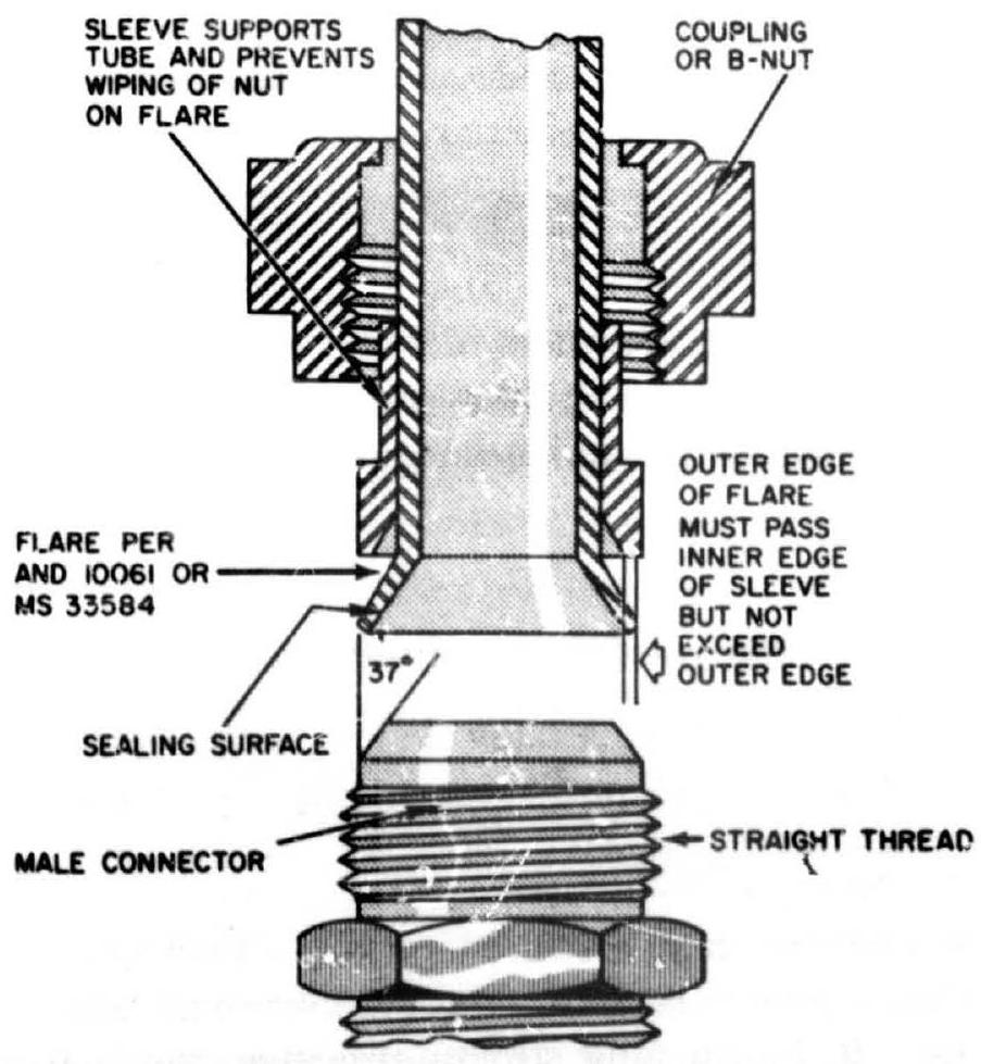 Figure 9-7.-3-piece flared-ube fitting per AND 10056 or MS33;56.
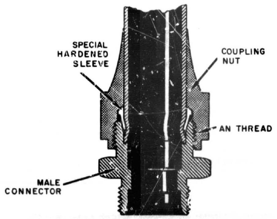 Figure 9-8.-Flareless tube fitting (Ermeto) per MS33514.
Table 9-3.-Minimum Bend Radii for StainlessSteel and Aluminum-Alloy Tubing [All measurements in inches]
| Tube OD | Wall thickness | Inside bend radii | Radii to center of tube | |
|---|---|---|---|---|
| 3/16 | Any | 5/8 | 23/32 | |
| 1/4 | Any | 3/4 | 7/8 | |
| 5/16 | Any | 3/4 | 29/32 | |
| 3/8 | Through 0.022 | 1-1/2 | 1-11/16 | |
| Over 0.022 | 1 | 1-3/16 | ||
| 1/2 | Through 0.028 | 1-3/4 | 2 | |
| Over 0.028 | 1-1/2 | 1-3/4 | ||
| 5/8 | Through 0.028 | 2-1/2 | 2-13/16 | |
| Over 0.028 | 1-3/4 | 2-1/16 | ||
| 3/4 | Through 0.028 | 3 | 3-3/8 | |
| Over 0.028 | 2-1/2 | 2-7/8 | ||
| 7/8 | Through 0.035 | 3-1/4 | 3-11/16 | |
| Over | 0.035 | 2-3/4 | 3-3/16 | |
| 1 | Through | 0.035 | 3-1/2 | 4 |
| Over | 0.035 | 3 | 3-1/2 | |
| 1-1/8 | Through | 0.035 | 4 | 4-9/16 |
| Over | 0.035 | 3-1/4 | 3-13/16 | |
| 1-1/4 | Through | 0.035 | 4-1/2 | 5-1/8 |
| Over | 0.035 | 3-1/2 | 4-1/8 | |
| 1-1/2 | Through | 0.035 | 6 | 6-3/4 |
| Over | 0.035 | 4 | 4-3/4 | |
| 1-3/4 | Through | 0.035 | 7 | 7-7/8 |
| Over | 0.035 | 5 | 5-7/8 | |
| 2 | Through | 0.035 | 7 | 8 |
| Over | 0.035 | 6 | 7 | |
| 2-1/2 | Through | 0.049 | 9 | 10-1/4 |
| Over | 0.049 | 7 | 8-1/4 | |
| 3 | Through | 0.049 | 11 | 12-1/2 |
| Over | 0.049 | 9 | 10-1/2 | |
| 4 | Through | 0.065 | 12 | 14 |
| Over | 0.065 | 10 | 12 |
Table 9-4.-Recommended Support Bracket Spacing for Tubing Assemblies in Engine Systems
| Tube size (OD), in | Maximum support spacing in inches | |
|---|---|---|
| Aluminum alloy | Stainless steel | |
| through . | 12 | 14 |
| through . | 17 | 20 |
| 1 and over . | 21 | 24 |
special hardened sleeve, which cuts into the tube wall. Flareless tube fittings may be used optionally in engine designs.
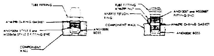 Figure 9-9.-Typical installations of tube fitting ends into AND10050 boss.
The tube fittings should be of the same material as the tubing. Fittings are designed to be as strong as the strongest tubing of like material used with the fitting. Design details and dimensions of tube fittings can be found from AND and MS specifications. In some cases, AN and MS parts are interchangeable.
The boss design for engine components, to connect AN tube fittings, is specified by AND10050. Figure 9-9 illustrates typical installation of tube fitting ends into the AND10050 boss.